
Author: Zixuan Wang
Mentor: Dr. Gino Del Ferraro
Shanghai Jianping HIgh Scholol
Part I
1.1 Electrostatic Phenomena
When we rub glass rods with silk, the glass rod become charged with negative charges. When we rub plastic rods with fur, the rods are charged with positive charges. After being rubbed with fur, plastic rods repel each other. However, if put the plastic rod close to a glass rod, they will attract each other. This kind of interaction between charges is called electrostatic force.
1.2 Electroscope
The electroscope is a tool to measure electrostatic force. It works by electrostatic attraction or repulsion and consists of two metallic leaves suspended from a metal hook. The leaves are inside a glass container to protect it from air currents. The leaves are connected to a metal ball which is on the top of the container. When a charged object is brought near the ball, the charges on the object cause the same charges move away toward the end of the leaves. The leaves are then spread apart due to the repulsion of same charges.
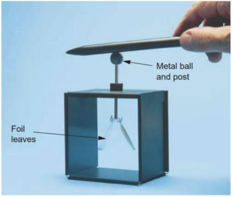
The electroscope can also quantify the amount of charge of an object. A larger charge causes the leaves to spread further apart. Electroscope can show the type of charges of two object. One can first bring an object in touch with the electroscope. This will cause the foil leaves to separate. Then, bringing the second object can be brought next to the electroscope’s post. If the two objects have same type of charges, the second contact will cause a further separation. On the contrary, if the leaves are brought closer than the two objects have different types of charge.
1.3 Benjamin Franklin’s idea
Charge produced on a rubber rod when rubbed by fur and charge produced on a glass rod when rubbed with silk have been found having different properties for a long time. They didn’t gain their names until Benjamin Franklin (1706-1790) introduced the concept “positive” and “negative” around 1750. He noticed stable fluid is present in all objects. During rubbing, they carry similar or different properties as some fluid is transferred from one object to another. Thus, he proposed that the charge on a glass rod when rubbed with silk be called positive. This concept is revolutionary, and Franklin’s model also approaches the reality more, which has electrons being transferred instead of “fluid”.
1.4 Conductors and insulators
Conductors are materials that permit electrons to move easily from one region of the material to another. For example, electrons can move freely within a copper wire. Most metals are good conductors, while most nonmetals are insulators. Insulators can prevent charge from leaving metal wires. Most metals are conductors, while most nonmetals are insulators. Within a solid metal, one or more electrons in each atom become detached and can move freely throughout the material. In an insulator, electrons cannot move freely through the material.
1.5 Coulomb force
Coulomb’s law is used to measure the electrostatic force. It is developed by the French scientist Charles Coulomb (1736-1806).
The force F can be expressed as:

Were q1 and q2 indicates the charges respectively, r is the distance between the charges, and k is a constant. When the charges have the same sign, the forces are repulsive; when they have opposite signs, the forces are attractive.
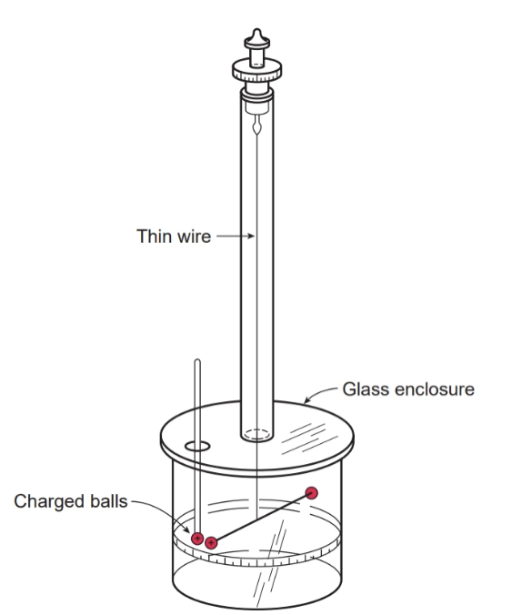
Figure 1.2 Torsion balance built by Coulomb. The degree of twist of the wire provides a measure of the repulsive force between the two charges.
In order to measure the weak forces between two charges, Coulomb invented a torsion balance. An insulating rod is suspended at the middle of an enclosure. Two small metal balls are attached at each side of the rod. Both balls are charged. Another ball with the same charges is put close at one ball. It then causes the rod to twist. If the torque needed to create the angle of the twist is measured, the forces produced by two same charges can be measured. Besides, in order to give two balls the same charges, Coulomb placed one charged ball into contact with an uncharged ball, thus divided the charges on one ball into two equal parts. By repeating this process, he can divide charges to one-half, one-quarter and so on.
The electrostatic force has a similar functional form than the gravitational force, we can see they all have inverse-square dependence from the distance:
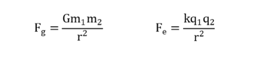
However, the gravitational force is always attractive. While the electric force depends on charges and can be either attractive or repulsive. For charged particles, the electrostatic force is the only force that is responsible to their interactions.
1.6 Electric field
Two positively charged objects at a distance exert a repulsion force to each other. If we place a negatively charged object instead of one positive object at the same place, the force, although still have the same magnitude, becomes repulsive. Therefore, the electrostatic force between two object depends on each object’s charges. We can define the Electrostatic field as a property generated by one charge only. This can be defined by dividing the Force F generated in between two charges by one of the charges as follows.
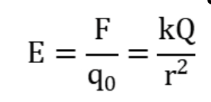
The electric field at some point is defined as the electric force F (experienced by a test charge q) divided by the charge q. In other words. The electric field equals to the electric force per unit charge. The object’s electric field is always present and its magnitude can vary by changing the distance from that object. If another charge q enters the field, the force it experiences is exerted by the electric filed of the original object.
1.7 Electric Field Line
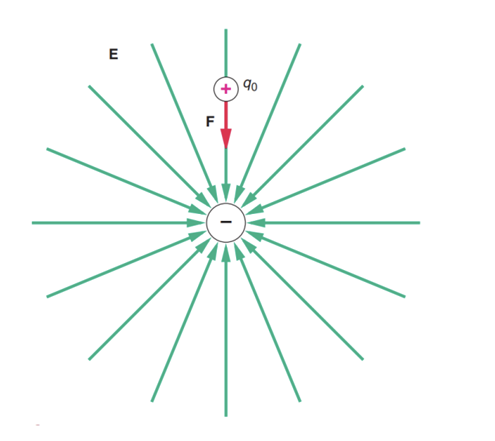
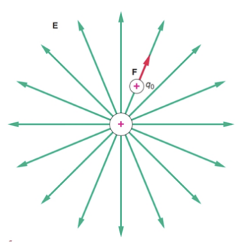
One can define electric field lines to visualize the direction of a given force or a given electric field. The electric field for a positive charge always points away from it, outward, whereas the electric field of a negative charge point towards it, or inwards.
The field direction of a single charge is the direction of the force a positive net charge experienced near the charge. We can find that the test charge is repelled by the original charge when placing near it. The test charge is attracted by the original charge.
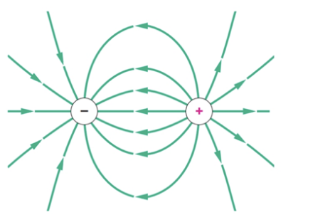
When placing two opposite charges together, they attract each other, so the electric field point toward the negative charge. On the left side of the negative charge, the field line is same to single negative charge’s, and on the right of the positive charge, the field line is also same to that of a single positive charge.
1.8 Electric Potential Energy
The electrostatic force is a conservative force, which means that we can define an electrostatic potential energy. This potential energy leads to the related concept of electric potential. As the change of kinetic energy equals the total work done on the object, if there is only electrostatic force act on the object, the work done by the electrostatic force equals the change in potential energy.
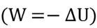
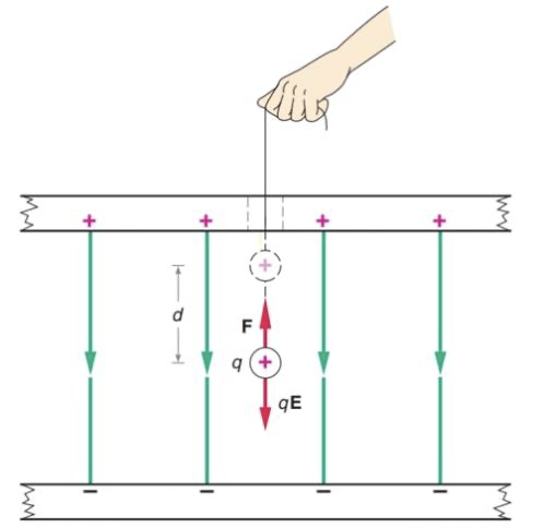
Figure 1.4 An external force F, equal in magnitude to the electrostatic force qE, is used to move the charge q a distance d in a uniform field.
In a uniform electric field as shown above, ![]() , If a positive charge moves downward (in the direction of E), the work done by the electric force is positive, so U decreases.
, If a positive charge moves downward (in the direction of E), the work done by the electric force is positive, so U decreases.
If the charge moves in the opposite direction of E, the work done by the electric field is negative. In other words, an external force is done on the charge, causing U increases. For positive charges, moving along a positive electric field decreases their electric potential energy, while for negative charges, moving along the positive electric field increases U.
Since we usually define U=0 when r is infinite, ![]() when moving a particle from infinite far to r. Therefore,
when moving a particle from infinite far to r. Therefore,
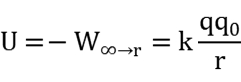
1.9 Electric potential
Electric potential is related to electrostatic potential energy in much the same way as electric field is related to the electrostatic force. The change in electric potential is equal to the change in electrostatic potential energy per unit of positive charge.

Its unit is V or J/C. Electric potential is also called potential energy per unit charge. Like electric field, V exist at a point even if there is no charge.
Figure 1.5 Electric potential decreases along the E field lines
Part 2
2.1 Electric Circuits
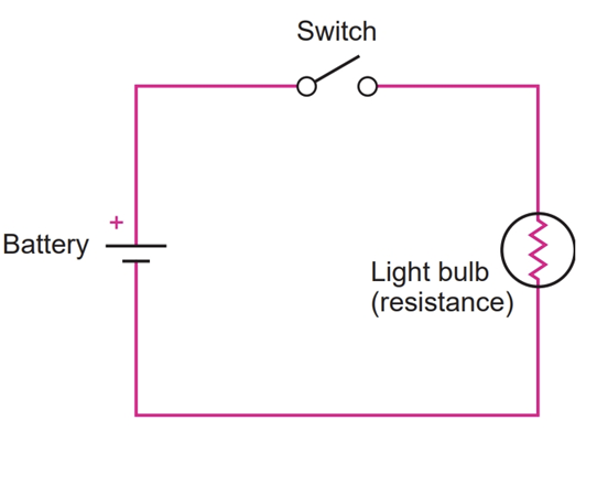
An electric circuit is defined as a closed conducting path that allows the electric charges in the wire to move from one region to another. Within a conductor, when there is no external electric field, the charges move randomly. Instead, if there is an electric field E is established inside the conductor, charges will experience a force and start to move in one direction. The charges also experience collisions with the metal particles when they pass through conductors. In other words, the kinetic energy supplied by the electric field is dissipated to heat the conductor, which keeps the charges from moving faster.
Electric circuits must be a closed circuit instead of an open circuit or a conductor. In an open circuit, an electric field E1 will let positive and negative charges accumulate respectively at two sides of the wire. These charges will then create an opposite electric field E2 , which will offset E1 and decrease the total electric field to zero.
As a result, we need a device, often called a battery, that act as an external force that can is in opposite direction to that result from E1 and carry the positive charges from lower potential to higher potential.
Therefore, a complete circuit must consist of a wire, a conductor (or resistance), and a battery.
2.2 Electric current
In a conductor, if the charges experience an electric field, they will start moving in a direction.
The net charge flowing through the circuit per unit time, or the rate of flow of electric charge is defined as current:

The standard unit of current is ampere, defined as 1 coulomb per second (1A=1C/s).
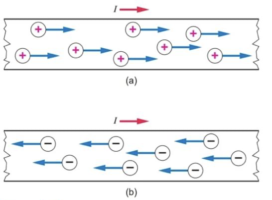
In different current-carrying materials, either positive or negative charges can be the moving charges. In figure 2.2, positive charges move to right, in the direction of the electric field, while negative charges move to the left, in the opposite direction. For negative charges that moves to the left, they create the same effect as the first case as the net charges on the right increases. In both case, positive charges flow to right, so we define current to be in the direction of the flow of positive charges. Current in this definition is called conventional current.
2.3 An analogy to the flow of water
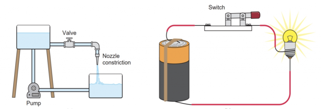
In a circuit, the charges move through an external conducting path due to the electric field caused by the potential difference at the two sides of the battery. As the positive charges moves from high potential to low potential, the potential of the charges is thus decreasing. In order to maintain the current, as charges pass the battery, the battery provides a force to lift positive charges from low potential to high potential. The work done by the battery increases the potential energy of the charges.
This is analogous to water flowing in a pipe vertically, as shown in Figure 2.3. Water flows down the pipe from high gravitational potential energy to low potential energy. Then, a pump lifts the water back to its original height and increases its potential energy. While batteries provide necessary potential energy for the charges, the pump guarantees the water to flow.
2.4 Electromotive Force
Electromotive force (emf) is the potential difference, or voltage, of a battery. It is actually not a force. Its equal to the work the battery does on every coulomb of charge that passes through it. It is, in other terms, a potential energy difference, or voltage, ϵ or V is the symbol for emf. The unit of emf is volt (1V=1J/C)
2.5 Ohm’s Law and Resistance
Ohm’s Law shows the proportional relationship between the current and voltage. It also shows the current not only depends to the voltage, but also on the resistance.
The relationship was discovered experimentally by the German physicist Georg Ohm (1789-1854). In symbols:

A quantitative definition of resistance R is:

While the definition of R is:

The unit of resistance is ohm (1Ω=1V/A)
The longer the wire, the greater the resistance; the thicker the wire, the smaller the resistance. Besides, the resistance also depends on the electrical conductivity of the material. Compared with resistance of water’s flow rate in a pipe, a narrow water pipe offers more resistance; the larger cross-sectional area increases flow rate. If the pipe is stuffed with cotton, the resistance also increases.
2.6 Series and parallel circuits
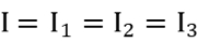
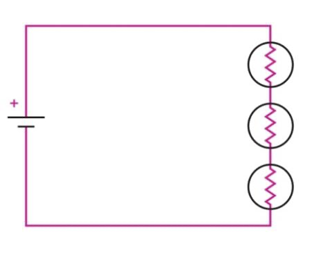
In a series circuit, the circuit elements are connected in sequence, lining up on a one after the other. In series, the current I remains the same through the path.
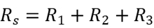
The total resistance of the combination Rs is:
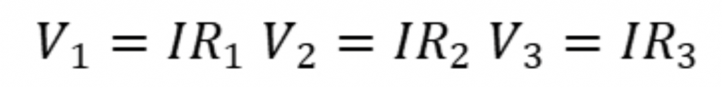
For each resistor, since they all have the same current, we can know their voltage respectively:
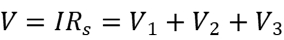
The resistance across two sides of the battery is:
Since the total resistance of a series combination is greater than any individual resistance, so connecting a bulb is series will make it glow less brightly.
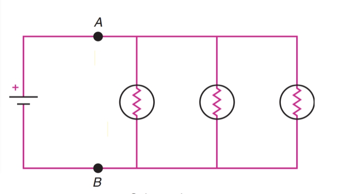
2.6.2 Parallel circuits
In parallel circuits, each resistors provides an alternative path for the current. The potential difference is the same across each element.
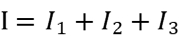
The total current equals to the sum of the three currents in the resistors:
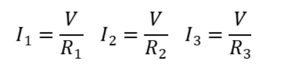
The current in each resistor is:
So the total resistance R is:
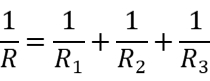
The total resistance of a parallel combination is less than any individual resistance. As the current in a bulb connected in parallel is independent to the adding of other resistors, connecting a bulb in parallel doesn’t change its brightness.
2.7 Electric Energy and Power
The negative and positive charges in a battery are kept at the opposite poles of the battery thanks to the chemical reactions happening inside the battery. This chemical reaction are generate by a chemical energy which keeps the positive and negative charges separated on the pole. This latter chemical energy corresponds to the electrical energy which is created within the battery and can be used through the electric circuit to move the charges from one point to another. As the charges pass resistors, the potential energy is dissipated as the charges collide with atoms in the resistors.
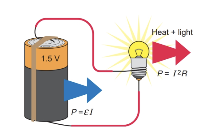
The rate of transferring energy from the battery is called power:

The unit of power is watt: 1W=1J/C. The power delivered to any resistor is:
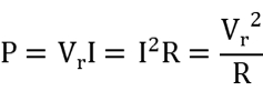
Where Vr is the voltage across the resistor and I is the current in the resistor.
Part 3
3.1 What are magnetic poles?
Of a bar magnet, one end is called a north pole or N pole, and the other end is called a south pole or S pole. Opposite poles attract each other, and like poles repel each other. This is similar to electric interactions. We can also describe the interactions between two magnets as one sets up a magnetic field around it, and the other magnet moves in response to the magnetic field.
3.2 Is the Earth a magnet?
In early years, people sail with a compass which always points to the north. The Earth’s north is defined by the direction of the compass’s north points. As a result, Earth’s geographic north pole is like a magnet’s south pole, which attracts the compass’s north pole. The earth’s magnetic axis, though, is not parallel to its rotation axis, so the compass’s reading derivates a little from the true north.
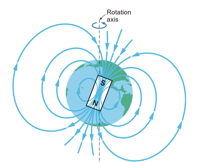
Figure 3.1 the earth’s magnetic field
3.3 Magnetic field lines
While magnetic poles may be similar to electric charges, unlike isolated positive and negative charges, magnetic poles always exist in pairs. When a magnet is broken to two, each end becomes a new pole. The magnetic poles in pair are called a magnetic dipole, and an isolated magnetic pole is called magnetic monopole, which is not yet discovered.
Magnetic field lines emerge from the north pole and go into the south pole. Different from electric field lines, magnetic field lines do not end at the south pole, instead, they form a circle back to the north pole.
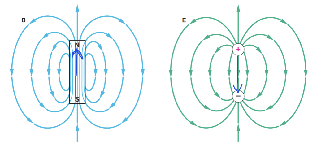
Figure 3.2 magnetic field lines and electric field lines
If we put a magnetic dipole in a magnetic field, the magnetic dipole tends to align with the magnetic field at its position due to magnetic attraction forces and repulsion forces.
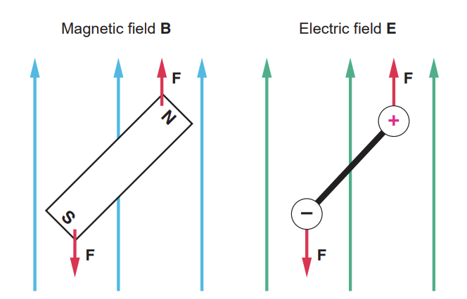
Figure 3.3 The behavior of magnetic dipoles in a magnetic field is also similar to that of electric dipole
3.4 An unexpected effect
The first evidence of the relationship of magnetism and electric current was discovered by Danish scientist Hans Christian Oersted. When he was giving a lecture, he surprisingly found a compass needle was deflected by a current-carrying wire. When the wire carries current, a compass placed directly over the horizontal wire deflects. As shown in figure 4, when the current is towards north, the needle deflects towards northeast.
The electric and magnetic interactions in this case around a straight, current-carrying wire forms circular magnetic fields. The magnetic field’s direction is determined by a right-hand rule. Point the thumb of your right hand in the direction of the current. Your fingers now curling around the wire in the direction of magnetic field lines.
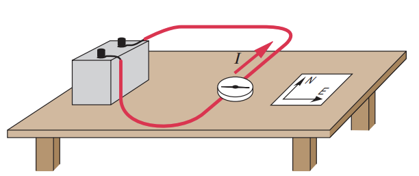
Figure 3.4 When the wire carries a current, the compass needle deflects.
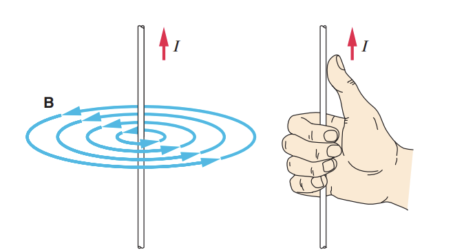
Figure 3.5 The right-hand rule gives direction of the magnetic field lines that encircles a current-carrying wire.
3.5 The magnetic force on a current-carrying wire
Since there are magnetic fields near a current, will this magnetic field exert a force to another current-carrying wire?
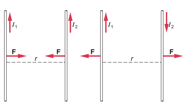
Ampere discovered that there is a force exerted to another current-carrying wire due to the magnetic field around the original wire. Ampere first ensured the force are not mainly caused by electrostatic effects. Then, he found out the magnetic force between two wires is proportional to the currents and inversely proportional to the distance r between the two wires.
This relationship can be expressed as:
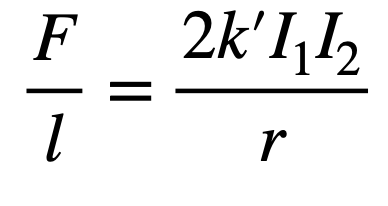
where constant k’ is equal to 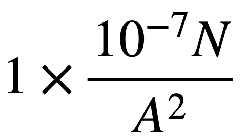 , I1 and and I2 are the current flowing through each of the wire, respectively, and l is the length of the wire. is the force per unit length of the wire. The longer the wires, the greater the force. The force between the wires is attractive when the currents are flowing in the same direction and repulsive when the currents are flowing in the opposite directions.
3.6 The magnetic force on moving charges
By experiments, we know that the magnetic force on a moving charge is proportional to the magnitudes of the charge. When its charge doubles, the magnetic force doubles. The force is also proportional to the magnetic field strength. If the magnetic field is stronger while the charge remains the same, the force is stronger. If we have a moving charge q which moves through a magnetic field B then the magnetic force also depends on the velocity of the charge. If the charge is at rest, it experiences no magnetic forces. At last, the force is only related to the component of velocity ![]() that is perpendicular to the field. When
that is perpendicular to the field. When ![]() is parallel to the magnetic field, the force is zero.
is parallel to the magnetic field, the force is zero.
The magnitude of magnetic force is given by:

Since![]() and
and ![]() are vectors, the direction of their product
are vectors, the direction of their product ![]() can be determined by a right-hand rule. First, point the index finger of your right hand in the direction of the velocity of the positive charge. Then, point the middle finger in the direction of the magnetic field. The direction of the thumb is then the direction of the magnetic force. The force on a negative charge is in the opposite direction of a positive charge moving in the same direction.
can be determined by a right-hand rule. First, point the index finger of your right hand in the direction of the velocity of the positive charge. Then, point the middle finger in the direction of the magnetic field. The direction of the thumb is then the direction of the magnetic force. The force on a negative charge is in the opposite direction of a positive charge moving in the same direction.
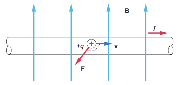
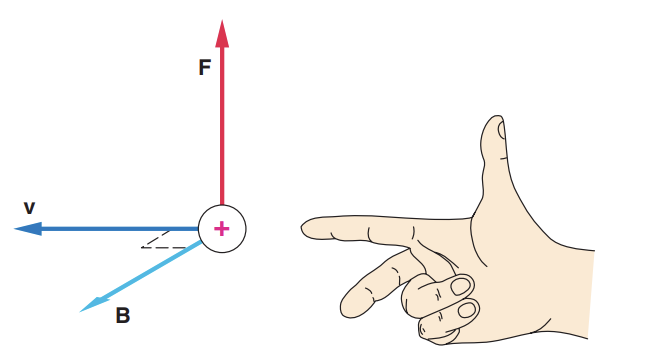
Figure 3.8 Right-hand rule for the direction of magnetic force on a positive charge moving in a magnetic field
About the author
Zixuan Wang
Zixuan is currently an 11th grade student at the Shanghai Jianping High School.