
Author: Winnie Shi
Mentor: Dr. De La Torre, Caltech
Shanghai Starriver Bilingual School
October 1, 2021
1.Introduction
Lightning rods, mostly made of copper, is a structure that protects buildings from being damaged by attracting flashes through electric-magnetic force and guide the current to the ground. After learning a bit about electricity and experiencing a night of thunder and lightning, I intend to explore how lightning rods work. Therefore, in this presentation, I will first introduce the historical research on lightning rods, and then explain how lightning rods work in general using electrostatic principles and some easy-to-understand analogies. I will then write a program to calculate the effective range of the lightning rod based on the Monte Carlo technique and finally propose a lightning protection solution in conjunction with the 3D street view.
2. The History of Lightning Rod
2.1 Franklin Kite Experiment
In 1746, Franklin turned his home into an electrical laboratory after occasionally discovering the electrical experiments of other scientists, and in a letter he described receiving an electric shock as “a numbing sensation from the beginning to the end”.
In 1747, thanks to Franklin’s discoveries, people stopped using glassy and resinous to describe electricity. They began to use positive and negative electricity.
In 1749, Franklin began to make analogies between lightning and batteries, and from then on lightning became palpable. He explained by analogy the bifurcation in lightning, the color of the lightning, and the deafening sound, and was determined to prove that lightning and electricity were directly related. in 1750, he began to focus his research on the protective devices for lightning. This was man’s first step toward the lightning rod
Fifteen years later, Franklin’s close friend recorded in his diary Franklin’s famous kite experiment. He took the risk of using a kite to try to get up close and personal with lightning. He even tied a key to the kite in order to attract an electrical charge. Even though the string of the kite was already made of insulating silk, this was still a very risky act considering the strength of the lightning bolt could even make the insulator relatively conductive. The conclusion of this experiment was that the key was seen to receive the electric charge brought by the lightning, and Franklin thus proved that lightning is electricity.
2.2 Tip Lightning Rod or Round-end Ones?
Almost simultaneously with the kite experiment, Franklin realized the fact that iron needles can conduct electricity, and tried to integrate this into the “lightning rod” invention. In his diary, he envisioned, “Could there be a way to protect people from sudden lightning strikes by inserting thin needles directly into clouds and pulling the electricity out of them before the lightning strikes the ground?”
Franklin focused on elevating the tip of the lightning rod, while Benjamin Wilson, a member of the Royal Court circle of George III, believed that the pointed lightning rod would attract lightning (and this property remained unchanged and became the main principle of the modern lightning rod) and was not as safe as the round-headed lightning rod. Most scholars at the time also supported Benjamin Wilson’s view, so much so that this eventually turned into a political showdown, with proponents of Franklin’s lightning rod being falsely accused of “trying to establish their own political group in England. The war between science and politics officially ended when an East India Company was struck by lightning, and Franklin’s spiked design is still used today.
2.3 Three primary Modern lightning rods
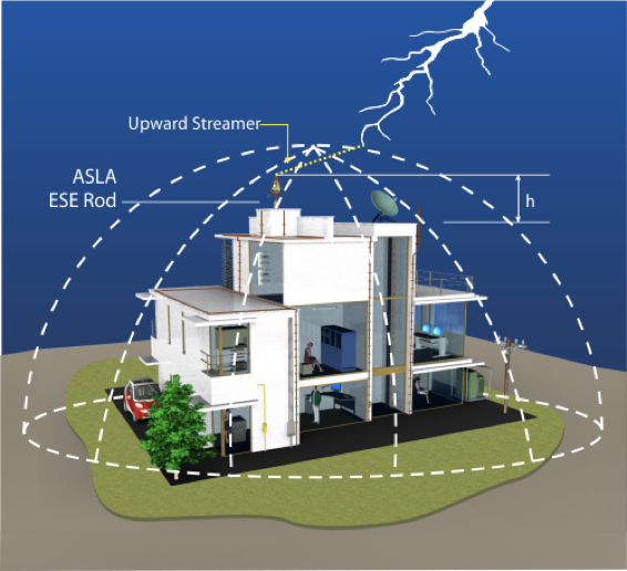
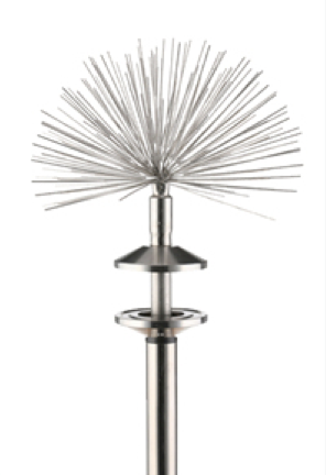
2.3.1 Early Streamline Emmision (ESE)
ESE systems are more similar to conventional lightning rods. They are designed to trigger early initiation of upward flow, which increases the effective protection range. This discharge trigger increases the probability of triggering a “streamline” discharge at or near the tip of the rod as the ionized “leader” approaches.
2.3.2 Charge Transfer System (CTS)
The CTS is characterized by its designated protection zone. It is the only system that deters lightning strikes, rather than encouraging them. CTS technology is based on existing physical and mathematical principles. The CTS collects the induced charge from the thunderstorm clouds in the area and transfers it to the surrounding air via an ionizer, thereby reducing the electric field strength in the protected area. The resulting reduction in the potential difference between the site and the clouds inhibits the formation of upward currents and thus reduces electric shocks.
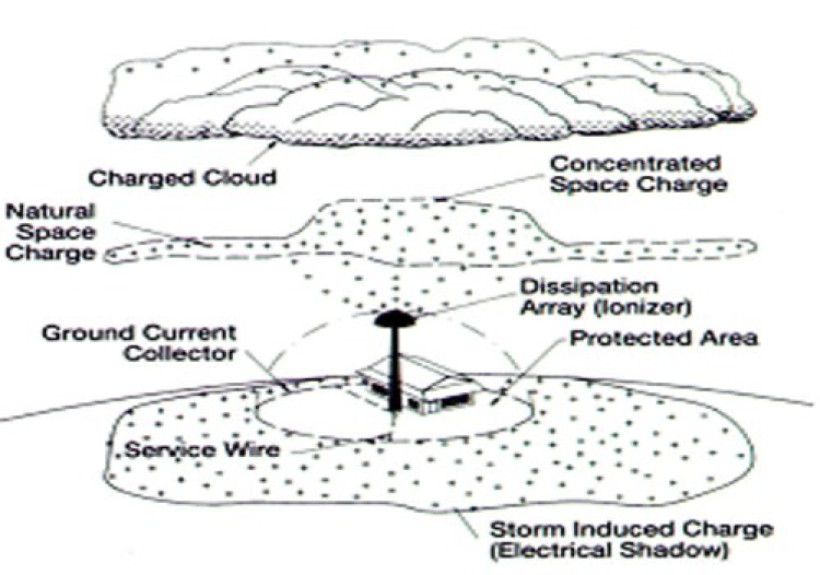
2.3.3 Dissipation Array System (DAS)
DAS is a special type of CTS. Based on the “protected area” of CTS, DAS can completely isolate a facility from direct lightning strikes during a thunderstorm by releasing the induced charge within the protected area to 55% of its pre-installation level in relation to its surroundings. When the electric field is reduced, the upward current does not get enough energy, and it is the connection of the upward and downward currents that is required for lightning to occur. Without energy, the connection cannot be made, so lightning cannot be generated.
3. The working principle of the lightning rod
3.1 Electron distribution
3.1.1 Electrons in the earth’s crust
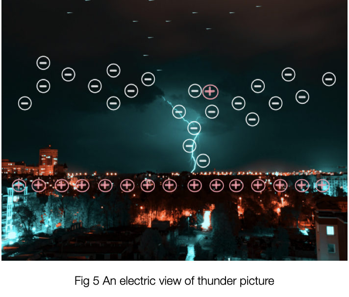
Before asking how lightning rods come into use, let’s first examine the function of electrons that makes lightning occurs. Before we go into how lightning rods work, let’s take a look at how electrons work to cause lightning. To begin with, the ground’s surface is made up of positive charges because the dipole cloud produces an electric field that forces electrons to flow to the earth’s core. The earth’s crust is plainly devoid of negatively charged electrons, resulting in a positively charged ground. Colors have been employed to depict the phase cancellation process, with yellow indicating negative charges and blue representing positive charges. The green hue created by combining blue and yellow is neutral, but the absence of either color gives it a bluish/yellowish appearance.
The positive charge upon the ground produces an electric field between the earth and the clouds, resulting in a negative charge covering the bottom of the clouds. And this electric field can reach 400,000 volts, creating a powerful electric field that lingers in the atmosphere. The procedure of positive and negative charge exchange in the clouds is essentially like an ion engine that repels the negative charge of the entire planet to the opposite side, according to the principle that different charges attract and the same charges repel.
We all know that when the electric field’s dipole reaches a particular level, clouds unleash lightning, which neutralizes the charge at the cloud’s bottom compared to the ground, and then the clouds repeat the process to rebuild the potential difference in the form of an exponential equation. Here’s a visual representation of this.
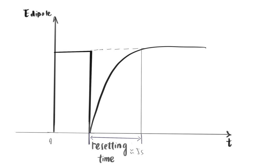
The time it takes to recharge is known as the resetting time, and we use it to determine the power of the ion pump described before, for which we have data of around 5 seconds. I=Q/T. When the experiment is replaced, the result is a cloud with a charge of -20C and a resetting time of 5 seconds.
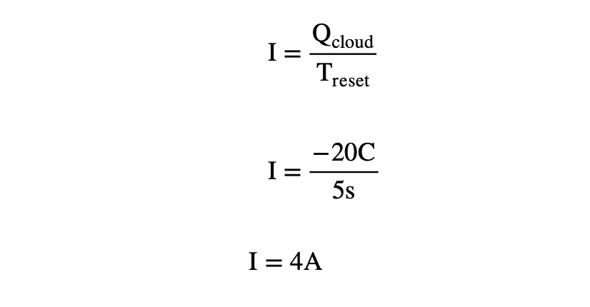
Despite the fact that 4 amps may appear to be a little quantity, comparable to double the current of a mobile phone charger (2A) or the current used in street lights (4A), it will inflict a great deal of damage due to the fact that it is released from a very small hole.
3.1.2 Electrons in clouds
Clouds that carries lightning consists soft hail particles and ice particles. Soft hails has more weight than ice particles, therefore they fall to the bottom during a thunderstorm while the small crystals were uplifted to the top. This falling process allowed negatively charged hails stay at the bottom(6-8km) and positively charged ice floats to the upper part of the cloud to 10km.
3.1.3 Generation of lightning
There are three major hypothesis about how lightning comes into place.
- The electric field inside a stormy cloud is far higher that what has been calibrated.
- Lightning is created via hydrometeors, which means water particles in the cloud
- Energetic runaway electrons initiate the lightning.
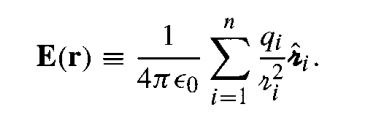
Because the overactive electrons (hypothesis 3) in the above figure are hydrometeors (hypothesis 2), ice crystals and water droplets traveling through the cloud, and the situation presented by hypothesis 2 usually boosts the electric field strength by a large margin, due to the equation of Coulomb’s law, these three points are actually interconnected.
It can be found that the electric field strength is inversely proportional to the square of the distance. Thus overactive electrons are in between many electrons of different charges, causing a huge electric field and thus the birth of lightning.
Most lightning is intra-cloud lightning, while lightning that occurs outside of clouds is divided into four main types, two from the ground to the thunderclouds, which are beyond the scope of this report, and two from the thunderclouds to the ground. One of them is downward lightning negatively-charged leader caused by a negative charge at the bottom of the cloud and a positive charge for activation, and the other is downward lightning positively-charged leader caused by a negative charge leading from the positive charge at the top of the cloud connected to the ground charged leader.
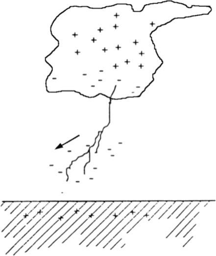
Fig 6 cloud-to-ground lightning flashes
3.2 Lightning propagation methods
The negative step leader, as its name suggests, will extend the length of the leader channel by step propagation. In the study of lightning pathways, early studies based on photography were skewed because some of the steps were too tiny to be seen with the human eye. The multiple-station dE/dt technique was utilized by J. Howard, M.A. Uman, C. Biagi, D. Hill, V.A. Rakov, and D.M. Jordan in 2011 to localize each step. When Step brings the lightning to the ground, the length charge is around 10-3C/m, and the earth sends a return stroke to contact with it, resulting in lightning. TThis generally happens in the conductor nearest to the elevation, since lightning, like an item in an automated pathfinding system, will want to walk on the side with the least “resistance,” that is, the side with the quickest potential reduction movement. Because the charges at the ground and at the bottom of the cloud are generally different, the ground attracts the leader in this scenario.
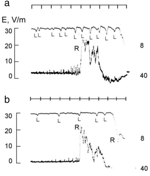
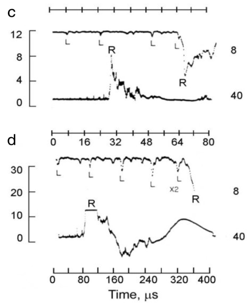
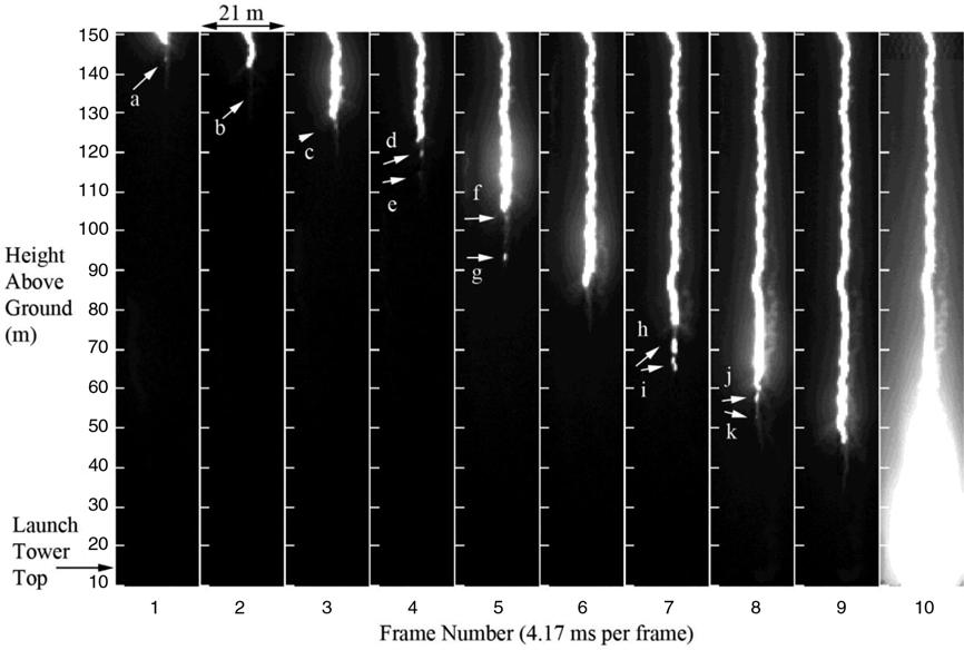
Fig 9. The figure shows the path of lightning in 10 video frames plotted by Biagi et al. The lightning originates from a 150 m high cloud layer and the return stroke is shown in frame 10.[Source: Adapted from Biagi et al.]
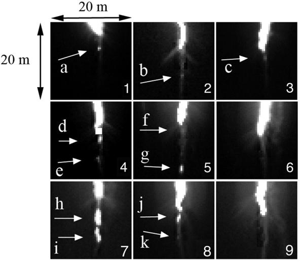
Fig 10 The figure shows a zoomed-in schematic of the first 9 frames of the leader, and it is easy to see the trend with increased contrast and brightness.[Source: Adapted from Biagi et al.]
3.3 How do conductors work?
A conductor is a substance that electrons are relatively free to move compared to the insulators, which is the property needed to create the lightning rod–any net charge resides on the surface because ρ=0 inside a conductor according to Gauss’s law. So that negative charges are attaching on the surface of the lightning rod, making it easy to be strike. The reason is, usually a ground is conductive and there are negative charges throughout the ground. When you put a conductor such as a metal on the ground, the electrons of the ground moved to the metal, and the protons in the metal moved to the ground until the metal and the ground are equipotential and the metal and the ground can be regard as a system because of the formula E = -⊽ V , Where E represents the electric field and it equals the negative product of divergence of electric potential. When the system is a closed loop the divergence is 0 so that there is no electric field and electrons are static again. The metal can then be seen as a whole with the ground. This reasoning is also valid for conductive buildings and lightning rods, which become more vulnerable to lightning strikes as if they were a mountain range raised on the natural landscape.
What will the lightning rods do to the lightning that it had intercepted? When lightning occurs, the lightning rod can attract the discharge channel of lightning, so that the lightning current flows from the lightning rod into the earth’s land, avoiding huge currents to cause damage to buildings, equipment, trees or injury to people or animals that happen to walk above the ground.
4. The effective area of lightning rods.
4.1 Monte Carlo Technique
Abhay Srivastava calculated the protection of the lightning rods by applying a mathematic model conducting rod using Monte Carlo technique. It is a computer simulated model that randomized the distribution of lightning strokes. It assumes a concave lateral surface of the cone, using the concept of striking distance ![]() in Golde’s formula, where ds means the striking distance, A=10 and σ = .65 are constants.
in Golde’s formula, where ds means the striking distance, A=10 and σ = .65 are constants.
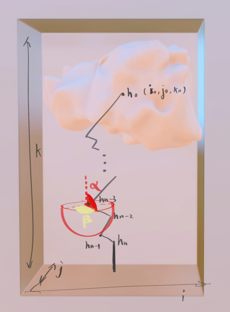
As the graph suggests, it initialized the sky with height k, the starting point of the lightning as h0, which will randomly stepping down towards the ground until it sees a postive charged object in its detecting sphere, which is assigned Hn. Hn-1 and Hn-2 are the last two steps from the striking point, and each point in this graph is given a three dimension coordinate.
The author assumes that the cube is 100*100*1000, and that a Cumulonimbus Cloud capable of storing lightning has a height of 500-16,000 meters.
The lightning will begin at a random location at the maximum height,1000m.
int[][] origin=new int[Math.random()*101][Math.random()*101];
In 5% to 80% range of the striking distance it generate some random variables to select the step length of leader.。Then it designate two angels of the spherical polar coordinates: the inclination angle α lying between π/2 and 3π/2 and the azimuthal angle β lying between 0 and 2π.
The mathematic formula is as follow. Iteration in Java should be used to infer where the lightning will strike. The loop terminates when the program determines that the lightning leader has reached the monitoring range, which is simulated as a sphere of radius 20m.
/*
*Precondition: it checks every step of the lightening
*Postcondition: true means that the lightning has successfully been *intercepted, and therefore will not be accounted as lightenings that have
*caused damage.
*/
Public boolean inRegion(Object leader,int r){
if(Math.sqrt(Math.pow(leader.getx()-rod.getx(),2)+Math.pow(leader.gety()-rod.gety(),2)+Math.pow(leader.getz()-rod.getz(),2)<=r)}
//Euclidean distance
return true;
return false;
}
Then comes the main program for generating the path, written according to the following mathematical equation.
public int[][] stepProcess(int[][] before,Object leader,int r){
int[][] after=int[][] before;
I=leader.getx();
j=leader.getz();
K=leader.gety();
while(k!=0&&!inRegion(leader,r)){
i=i+r*Math.sin( )*Math.cos(β);
j=j+r*Math.sin( )*Math.sin(β);
k=k+r*Math.sin( );
}
if(inRegion(leader,r)){
return before;
}
else{
after[i][j]=after[i][j]+1;
return after;
}
//the higher the number in the array is, the more dangerous is the area
}
After running the program, I tested 1000 times, assuming 10 strikes per year in this area, which would be all the lightning this virtual area has suffered in 100 years, and drew a graph of the conclusions drawn, where the yellow area represents relative safety(have been struck once), green represents absolute safety, and red represents danger(more than once).
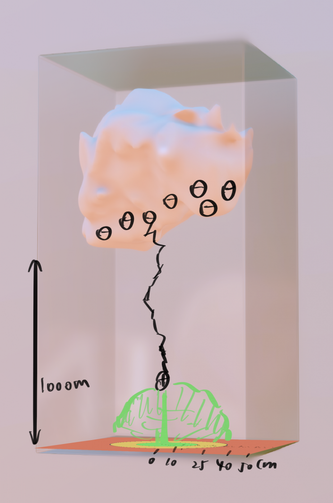
Fig 12/13 The output of the program
4.2 Real Life Application
In the 3D street view of Gaudet Map, I intercepted a dense map of high-rise buildings of about 1000*1000 and used the model for the simulation of lightning rod placement. It is assumed that all the buildings need protection, but we can ignore the open space. Here are the before-after graph of the map. When lightning rods were applied in that area, it meant to make sure every building to stay in the green or yellow circle of fig 12/13, which take the height of the lightning rods, r, as a variable and execute the program.
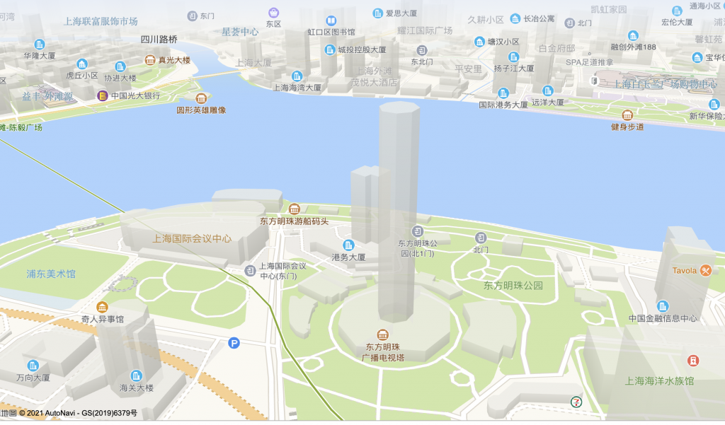
Fig 14 An actual overview of Lujiazui
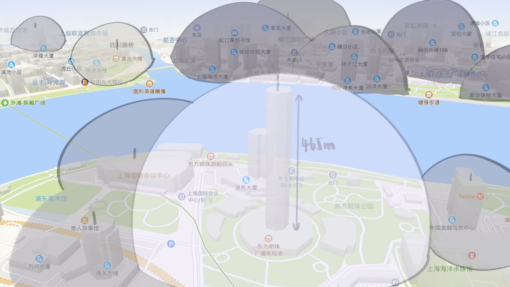
Fig 15 Protection after applying the program.
5. Reference List
1.“Modern Lightning Protection Lightning Rods with Lightning Eliminators.” Edited by LEC By admin, LEC, 19 Sept. 2018, www.lightningprotection.com/lightning-rods-are-old-new-lightning-protection-part-3/.
2. J. Howard, M.A. Uman, C. Biagi, D. Hill, V.A. Rakov, D.M. Jordan, Measured close lightning leader-step electric-field-derivative waveforms, J. Geophys.
Res. 116 (2011) http://dx.doi.org/10.1029//2010JD015249.
3. E.P. Krider, C.D. Weidman, R.C. Noggle, The electric field produced by lightning stepped leaders, J. Geophys. Res. 82 (1977) 951–960.
4. Srivastava, Abhay, and Mrinal Mishra. “Lightning Modeling And Protection Zone Of Conducting Rod Using Monte Carlo Technique – ScienceDirect.” Lightning Modeling And Protection Zone Of Conducting Rod Using Monte Carlo Technique – ScienceDirect, Www.sciencedirect.com, 13 June. 2013, https://www.sciencedirect.com/science/article/pii/S0307904X13003478?via%3Dihub.
“Franklin’s Lightning Rod | The Franklin Institute.” The Franklin Institute, Www.fi.edu, 8 March. 2014, https://www.fi.edu/history-resources/franklins-lightning-rod.
5. Godwin, Ian . “Franklin Letter To King Fans Flames Of Lightning Debate › News In Science (ABC Science).” Franklin Letter To King Fans Flames Of Lightning Debate › News In Science (ABC Science), Www.abc.net.au, 26 March. 2003, https://www.abc.net.au/science/articles/2003/03/26/816484.htm.
6. M. Vargas, H. Torres. On the development of a lightning leader model for tortuous or branched channels – Part II: model description
7. J. Electrostat., 66 (2008), pp. 489-495
8. M.A. Uman, The Lightning Discharge, Academic Press, London, 1987, 376 pages, revised paperback edition, Dover, New York, 2001.
9. K. Berger, Blitzstrom-Parameter von Aufwärtsblitzen, Bull. Schweiz. Elektrotech. Ver. 69 (1978) 353–360.
About the author
Douyun (Winnie) Shi
Winnie is a Physics learner at the Starriver Bilingual School in Shanghai, China.